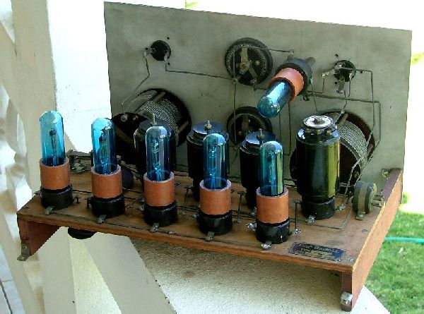
The first
problem encountered was bad tubes. All 6 of them. Two had
open filaments and the others had virtually zero emission. A bad
way to start the project. There's a number of equivalents
for these tubes but they are equally difficult and expensive to
locate. In those days different manufacturers used their own
numbers for the same tubes. I made a few half-hearted bids on
ebay.de and decided I best embark on a new plan.
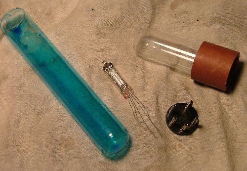
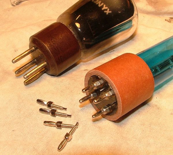
That plan was to use sub-mini replacements (5676 and 5672) as are
sometimes used to replace WD-11/12 and 99s in American sets. I
did not want to destroy the original tubes to salvage the bases so I
fabricated my own. The original tubes use a thin banana-pin
pinout and the socket itself simply has hollow tubes with no gripping
mechanism for the contacts. I made my base out of 1" ID phenolic
tubing and fashioned a disc for the bottom out of plexiglas. The
actual pins are a miniature banana pin found thru
Jameco.
Expensive little devils! The glass is made from 25mm test tubes
(shooter tubes!) cut to size with a Dremel tool using a diamond cutting
disc. I tinted the glass with a solution from a craft
store. The glass fits the tubing perfectly and is held in place
with silicon sealant so they are easily re-enterable.
(this
base
is from another project)
Will they work? I sure hope so. I'm not there yet.
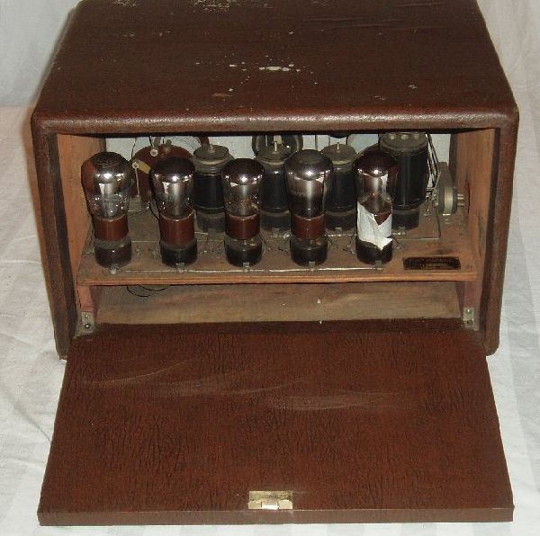
A note on the tube sockets. The same sockets are used for the
tubes as well as the IF transformers. These use a piece of brass
tubing peened out on the bottom to make contact with the lugs. I
had three that had lost electrical contact due to oxidation and one
other that read a high resistance. I had to remove them and clean
and solder the 'riveted' connection. I'm not sure what material
these are made from - its not Bakelite...and the IF coils use the same
material. They will crack with little or no provocation.
*
* * *
The Transformers and coils.
It was clear I had some problems to deal with regarding the IF
xfmrs. Two of them rattled inside and there was no continuity on
one of the windings. The screws apparently tend to work loose
inside of these things for lack of a lockwasher having been utilized.
Fortunately, the 1st IF was intact although it too rattled. Good
thing because its a fairly complicated one.
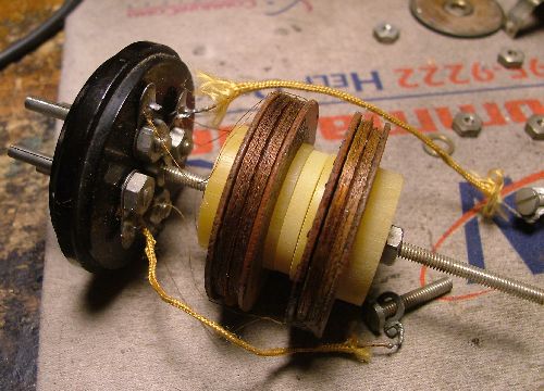
What you see here TWO individual coils in parallel making up both the
primary and secondary side. Wire gauge is in the mid-40s and
separation between the two pairs is 7.5mm. On the primary I
measured 9.0mH with 56 ohms DC resistance. The secondary measured
9.7mH and 63 ohms DCR.
(or
vice versa?) I made no attempt to separate the two coils on
either side. You can see the slight difference in side in the
photo so it would seem the slight difference in measurements is
intentional.
The caps utilized in this xfmr appear to be 540pf (marked 0,54)
Crunching the numbers suggests that this gives a slight stagger tuning
of about 2.5 kc. One of my caps is defective.
Note that the wires lead up to the 'hot' side of the individual caps
but they share a common 'cold' side by virtue of the mounting screw
which is connected to the secondary cold side. I'm not really
sure why this was done.
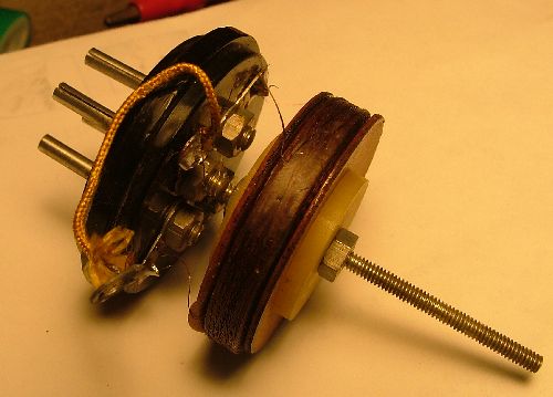
Here's the #2, 3, 4 transformers
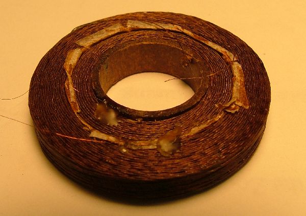
And here's a pic of the coils, primary is inside of the secondary.
.
Again, very fine mid-40s gauge wire. The inner primary was open
on the first one and testing revaled it was open in more than one
place. I was able to snag a wire at the very inner and outer
extremes and tacked on new leads with a strand of #46 from a litz
wire. I might add that this repair took about 2-3 hours and
doesn't qualify as 'radio fun'.
The specs on the xfmrs is as follows. Primary ~8.7mH, untuned,
100 ohms DCR. Secondary 42mh tuned with a 160pf cap in the top,
245 ohms. This gives resonance at ~60 kc. My three
calculated to be at 60.6, 60.9 and 61.8 when measured out of
circuit. The caps (marked 0,16) ranged 66, 98 and 142pf.
Safe to say that these caps have not held up well over the years and I
will fudge in the additional capacitance with some ceramic discs hidden
underneath the original assembly.
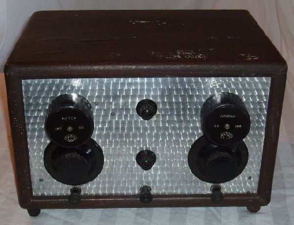
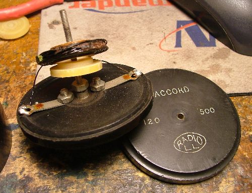
In comparison, the front panel plug in coils are a piece of cake.
They are wound with a good size wire - 22 or 24 gauge - and relatively
simple. Here's the BCB RF coil (120-500 meters). It too had
come loose internally but no damage occured thanks to the large
wire. It measures 67uH which corresponds with the specified
tuning range using the 70-1100pf tuning cap. I also have another
RF coil missing its cover, it measures 3.2mH which suggests ~85
to 335 kc or maybe it was originally listed as 1000-3500 meters.
Note that although the variable capacitors both appear to be two-gang
units, the gangs on both are connected in parallel.
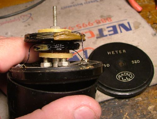
The oscillator (HETRO) coil is wound with the same large wire. It
is marked as 180-520 meters. 65uH and 296 uH respectively on the
windings.
Well, that was a fun exercise. Now we know whats inside of them
and the repairs have been made. One less thing to troubleshoot at
fire-up time.
*
* * *
Schematic
* *
* *
It Works!!!
This
evening I put it all together
for the smoke test. Much
to my surprise it fired right up!!!
I used 90 volts as the B+ voltage and 67.5 on the
oscillator. I found the oscillator wasn't real happy with that
voltage and increased it to 90. Actually the circuit does well if
the B+ is at 67.5 but the oscillator definitely wants 90. The
C-minus for the output tube seemed best at -3 to -3.5 volts and when it
was all trimmed out and playing a filament voltage of around 0.8 volts
at the tubes seemed to be the ideal setting. Audio quality is not
remarkable.
I
made a quickie tuning chart for the oscillator and it tunes from about
600kc to 1750kc so that gives full coverage from 540 to 1690 kc.
Operationally
the set is very well behaved and not at all difficult to tune.
The verniers are some of the nicest I've ever used. Of course
there's the image issue with the 60 kc IF but the rf input tuning is
quite sharp even with my random wire antenna and does a fair job of
image rejection - noticeably better than my homebrew Ultradyne.
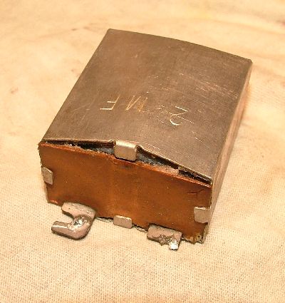
After
about an hour of operation it died. Something was pulling down
the B+. I disconnected it and re-connected again and it ran for a
few minutes more. I looked under the chassis and lo and behold
the 2mf paper cap had gotten hot and swollen up. Duh, I should
have restuffed those caps to start with. There's only two, the
2mf and a 0.5mf and that situation is now corrected.
In
summary, I'll say that Mr. Levy did a good job with this set. I
don't know how it would compare using the original tubes but I would
suspect that they weren't as hot gain wise as the modern
sub-minis. It receives well, comparable to any typical 5-tube TRF
set with the obvious benefit of having selectivity at the top end of
the band.
-Bill
Meacham, 10 May 2006