Exray's Lacault Ultradyne Superhet Project.
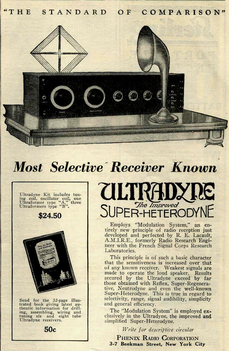
Robert E. Lacault of the French Signal Corps developed his own version of
the circuit which he dubbed the Ultradyne to distinguish it from other superheterodyne
circuits. The Ultradyne came out in various kit configurations, the most
prevalent seems to be the L-2 model which utilized 8 tubes and regeneration
available at the first detector.

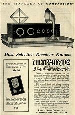 Click on the links to see the old ads
provided by Dale Davenport
* * *
After some interesting discussion on the Antique Radio Forum - and being
curious about how this circuit was supposed to work - I checked the junkbox
and sure enough it appeared I had enough pieces and parts to attempt building
an Ultradyne-wannabe from scratch.
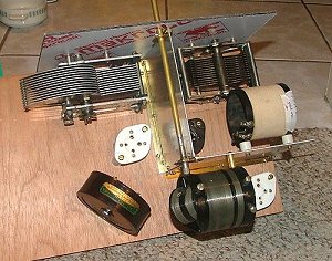
A 24 x 9 x 3/4 piece of wood from a previous project served as the base.
Cramming an 8-tube circuit on a 24 inch board is tighter than it might seem
- especially when one wishes to minimize undesired coupling between coils
and the like.
Before jumping into such a major project with both feet I decided to first
build up the RF (osc + mix) stage and see if it 'really' worked as there
was some initial doubt by me and others if there were errors in the published
schematics or if such a circuit was simply another 'wannabe' method of heterodyning.
I found an old WIRCO variocoupler assembly to use for the regenerative RF
input. The Wirco was a mess. It is wound with BARE wire and the windings
had slipped around. I got them all back into place and gave it a light coat
of varnish to hold everything in place.
The Wirco coil is one area where I strayed from the original design because
the L-2 circuit utilizes 2 coils in series for the resonant RF input. One
of the coils, the larger inductance of 45 turns, can be substituted by an
external tuned loop antenna while the smaller portion (20 turns) remains
on the chassis to provide coupling for the regeneration scheme. Its worth
noting that many superhet receivers utilize, or at least make provisions
for, an external loop. On the surface this may seem simply like a consumer-oriented
gesture but in reality a big external loop can provide much higher selectivity
than an onboard coil. This is quite important with such a low IF frequency
to minimize images and provide selectivity.
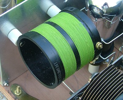
The oscillator coil is pretty straightforward to wind and I wound my own
version on a 2.5 inch former using nice green cotton-covered wire of about
32 gauge.
The two tuning capacitors are SLF (straight line frequency) versions from
the junkbox. Unfortunately I did not have a nice looking pair of matched
capacitors. These are about 475 pf each.
The oscillator section resides in a semi-shielded compartment made from aluminum
plate.
After rigging up this "sub-assembly" I gave it a smoke test to see if it
worked. I simply loaded it with one of the IF xfmrs and connected a diode
and hi-impedance phones to the output side. Hurray! It indeed "worked"
and that was all the indication I needed to proceed with the project, the
remainder being pretty straight-forward.
* * *
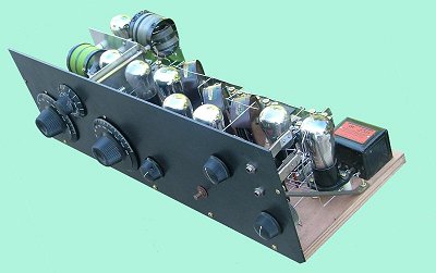
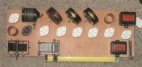
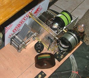
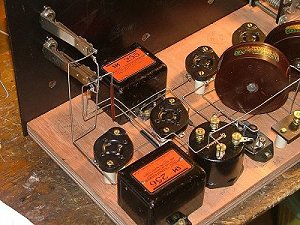
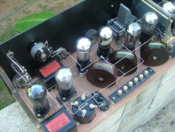
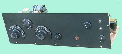
I refined my physical component layout a few more times until I got things
to fit efficiently and neatly. The sockets I used are the ebay chinese ceramic
ones painted black and mounted on standoffs. I might mention that part of
my motive in building the set was to not bankrupt my parts budget so I didn't
go out and buy 'real' breadboard sockets. There's also an advantage here
in having the sockets up on 3/4" standoffs as it allows a bit of vertical
spacing for wiring connections to the tubes.
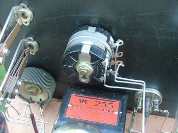
I had 3 old Victoreen 170 RF (IF) transformers in the junkbox and had to
build one additional xfmr from scratch. The nice pair of Silver-Marshall
audio xfmrs came from John Goller (K9UWA) and fit well into this scheme.
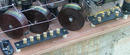
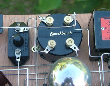
I fabricated a battery terminal board and an antenna connection board with
off-the-shelf brass hardware and Garolite scraps. When the wiring was at
about the 80% point and everything seemed to fit I added the front panel
made of black Garolite. The grid leak is a Freshman combined adjustable
type (250 pf and >5 megohm) (thanks, Lou).
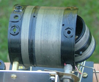
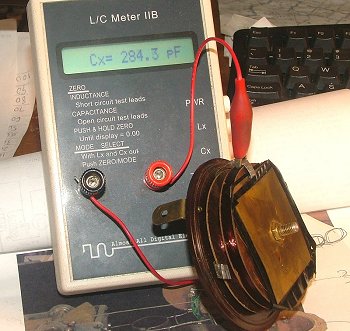
First order of business was to check out the Victoreen xfmrs and see what
they were all about. Not knowing their resonant frequency, actually not
even knowing that they were tuned, I went inside to measure inductance, etc.
I found out that they are indeed tuned to ~60kc. I noticed that the inductance
varied quite a bit between the three and that there was a 'sandwich' type
cap in the ~300pf range to bring the secondary into resonance. Not having
a 60 kc signal generator I simply went with accurate LC measurements to tune
them. I quickly noticed that their values were pretty sloppy and they were
falling over a range about 5-10 kc wide. They probably aren't so sharply
tuned to make that a big deal but they were erratic in how the bolt was tightened,
etc.
Below are some typical numbers for the Victoreen 170 WITH THE BRASS CAPACITOR
REMOVED. Note that the DC resistance numbers don't necessarily correlate
with inductance. The windings ranged from very loose to fairly tight. Wire
seemed to be #37 gauge on both windings.
|
Pri mH
|
Sec mH
|
Cap pf
|
Pri DC R
|
Sec DC R
|
1
|
5.468
|
22.81
|
308
|
46.6
|
107.4
|
2
|
5.978
|
23.17
|
303
|
45.5
|
106.6
|
3
|
5.161
|
21.52
|
327
|
44.5
|
105.2
|
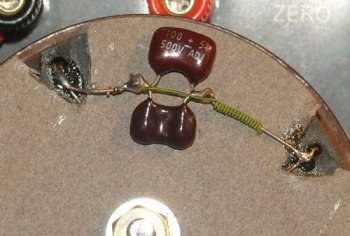
The caps were made with brass plates and one end of the cap is connected
to the brass mounting support. In order to get a accurate inductance measurement
I not only had to disconnect the caps but I had to remove the plates and
disconnect the connection to the mount since the presence of the brass substantially
lowers the inductance. Then I could calculate my own value of fixed capacitors
to install. I tuned them to a gnat's hair, all three fell into the range
of 300-325pf. I used a combination of silvered-mica caps plus a few pf
of gimmick capacitance as needed. Now they are solid and the values aren't
shifting around as before. This was a fret in the mid-20s since the guys
back then didn't really have efficient ways of tuning their coils and xfmrs.
This exercise was somewhat important because I still had the challenge of
building one additional xfmr from scratch. With the data at hand that turned
out to be simple. Oh, I almost forgot to mention, one of the Victoreens...the
only NOS/NIB one...had an intermittent short in the primary winding! I unwound
it and rewound it and it seemed ok. Must have been a pinched wire?
* * *
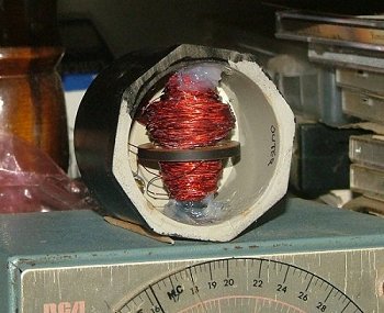
The various articles on the Ultradyne show how to build and wind the IF xfmrs.
Unfortunately that was no help for my project because I needed one that would
be consistent with my 60 kc Victoreens. The original L-2 transformers are
set up for 120 kc IF. From the
previous work on them I knew the turns ratio (2:1) and had a feel for the
number of turns to reach the desired impedance. Not having any wire smaller
than #30 in the shack I proceeded to wind with #30 on a short piece of -61
ferrite rod. #30 seems like small wire until you wind 600 turns of it on
a form! Then it seems awfully large. Anyway, I scatter-wound 600 turns
on one side and 300 on the other. With the help of the ferrite I had 11.99
mH on the tuned secondary side which resonated at 585pf.
This was all mounted inside a PVC plumbing cap with some silicone goo.
With the brass terminals mounted on top it is very much in the style of some
of the commercially made xfmrs of the era.
Update: 3 Jan 2006. I have acquired
some of the original Ultraformers and the
specs and details can be found here.
* * *
Now it came time for the wiring. I had two options available here in the
shack. Some #12 square tinned buss wire from AES or some round #16 tinned
soft drawn copper. After some trial and error with the #12 I'll have to
give anybody credit who built a complex radio like this one using such large
heavy wire. It was too much for me. The #16 worked out nicely and I'm having
fantasies of rewiring it totally with ~#16 brass rod since the soft drawn
wire is a bit difficult to keep neat.
Other than simple sets I have never wired anything major with this style
of wiring. That in itself was quite a challenge but I had a lot of fun doing
it. Measuring, cutting, forming each wire piece was a mini-project in itself
and it became more challenging as more wires were added. Obviously the goal
is to wire it in such a way than minor accidental bumps will not create shorts
while at the same time not being dependent on a bunch of spaghetti tubing.
I'm quite satisfied with the result. If I were to go back and rewire with
the brass rod it would be fairly simple now that everything is measured and
placed.
I had to do some scrounging for suitable rheostats and made do with what
I had on hand. I used a 6-ohm for the two audio tube filaments and a 20-ohm
for the detector filament. A 'modern' 1950's 600-ohm L-pad was pressed into
service for the bias potentiometer on the first three IF stages. Ideally
there should be a rheostat for the First Detector too. Some circuits show
one on the First Detector PLUS Oscillator but my oscillator seems to drop
out at around 4 volts so thats not a very good idea. Also ideal would be
a rheostat for the 3 IF gain stages. I see that only after firing up the
set...it has LOTS of gain and would be more manageable with that additional
control.
Also I didn't see an immediate need for an Audio Jack on the Detector Output.
I put one after the First Audio and on the Output. One on the Detector output
would be very handy because after only the First Audio stage one has to turn
everything down for a comfortable listening level with fones.
Luck. My well thoughtout parts layout seems to work. There is NO sign
of instability in the IFs or Audio. No feedback oscillation and there's
not a single bypass cap in the set! I'm in the stages of tweaking out
the alignment and seeing what is what. So far I'm very impressed with the
radio and its a cool and simple set to operate. Its still not as smooth
and bump-free as a TRF and I imagine this had something to do with the persistance
of TRF sets for several years afterwards in the consumer market.
* * *
Now the next stage of the project begins! My plan was to get it all wired
up THEN remove everything from the board to finish off the wood with stain
and lacquer. I know that sounds backwards but there's no way (for me) to
build something like this without munging up the breadboard finish. Then
there's the brass rod idea. Then there recouping all those ceramic spacers
and replacing them with black Garolite ones. Maybe add another rheostat
and a voltmeter? Not to mention general tweaking of the circuit - my osc
freq is WAAAY low so I have some harmonics running amuck. You certainly
don't want unnecessary harmonics with a 60kc IF. Oh, and not lastly, I have
aspiriations of kluging it into a Sparton 5-26 cabinet I have here if everything
else gets done!
I have a lot of people to thank that share the same enthusiasm for encouragement,
explanations, parts, etc. You know who you are. Every tidbit of assistance
is much appreciated. This is a great project!
Updated 3 January 2006