 Midwest 162-R
Technical topics...
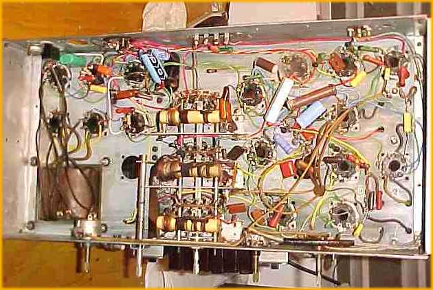
The first problem I met was deteriorated wiring. All rubber insulated wire was used and it had dry-rotted and had to be replaced 100%. Apparently this isn't true of all these radios because some use cotton covered wire.

The radio was fully recapped and all resistors checked. The published schematic has a number of errors and I had to sort them out as I went. I have kept my notes and will try to draw up a new diagram for posting here.

The radio was purchased with no tubes or speaker. The original tubes appear to have been metal-based glass ones with some slip on shields. I simply purchased a full set of metal ones and have observed no operational differences.
The original speaker was a 6x9 field coil type. Unobtainable. The original speakers in these sets apparently weren't up to par for the amount of audio that they had to handle. I substituted a 6x9 car radio speaker and a 500 ohm, 25 watt resistor for the field choke. By adding in an extra 22uf of filter capacity, there is no audible hum.
One serious problem was a damaged bandswitch section. That could spell junkpile for a radio like this, but Mike The Midwest Guru was able to supply a replacement one. I was very fortunate to have found one.

The set has a built in wire loop antenna around the back of the cabinet and uses a fancy scheme of switching and tuning it between bands. It is very effective and my outdoor antenna adds only minimal advantage.
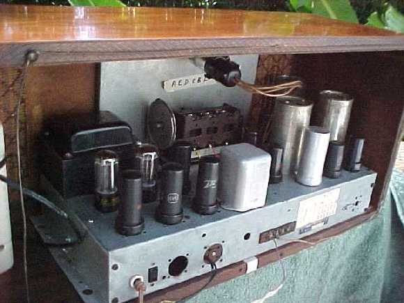
The cabinet was in pretty good shape and only needed a bit of regluing. I refinished it with lacquer and it really looks nice now. Oh, another 'cheap' aspect...one side of the cabinet is a burl veneer like the front, the other side is a very straight grain! I have the original plastic knobs but they are rather distorted and fragile. So, for general use I will stay with the wooden knobs shown in the pictures.
For more info, e-mail me...
Return to Sparkbench Home Page